
ITB TECHNICAL RECOMMENDATION Copal System balcony railings
ITB® Instytut Techniki Budowlanej
[ITB® Building Research Institute]
Member of the European Union for Technical Approval in Construction - UEAtc
Member of the European Organization for Technical Approvals - EOTA
Series: TECHNICAL APPROVALS
ITB TECHNICAL RECOMMENDATION
No. RT
The Building Research Institute in Warsaw at the request of the company:
Copal Sp. z o.o. ul. Sikorskiego 78,
confirms suitability for use in construction of the products under the name of:
Set of elements for making Copal System balcony railings
to the extent and on the terms and conditions set out in the Attachment, which forms an integral part of this Technical Recommendation.
|
Expiry date: |
'[oblong company seal with the state emblem of |
|
19 September 2018 |
the Republic of Poland in the middle and wording |
|
|
in the rim as follows] : Instytut Techniki |
|
|
Budowlanej [Building Research Institute] |
Attachment:
General and Technical Specifications
Director Instytut Techniki Budowlanej [Building Research Institute] Jan Bobrowicz
[signature illegible]
Warsaw, 19 September 2013
ITB Technical Recommendation No.
RT
any other form of excerpts hereof shall require a written agreement from the Building Research Institute .
ATTACHMENT
GENERAL AND TECHNICAL SPECIFICATIONS
TABLE OF CONTENTS
|
1. |
NATURE AND PURPOSE OF RECOMMENDATION .................................................. |
3 |
|
2. |
RECOMMENDED ITEM ................................................................................................. |
3 |
|
3. |
INTENDED USE, SCOPE AND CONDITIONS OF APPLICATION................................. |
5 |
|
4. |
TECHNICAL AND UTILITY PROPERTIES. REQUIREMENTS. .................................... 6 |
|
|
|
4.1. Properties of materials............................................................................................. |
6 |
|
|
4.2. Properties of the railings.......................................................................................... |
6 |
|
5. |
PACKAGING, STORAGE, HANDLING ........................................................................... |
9 |
|
6. |
ASSESSMENT OF CONFORMITY ................................................................................ |
9 |
|
|
6.1. General principles ................................................................................................... |
9 |
|
|
6.2. Initial type testing .................................................................................................. |
10 |
|
|
6.3. Factory production control...................................................................................... |
10 |
|
|
6.4. Testing of finished products................................................................................... |
11 |
|
|
6.5. The frequency of testing ........................................................................................ |
11 |
|
|
6.6. The test methods................................................................................................... |
11 |
|
|
6.7. Sampling for testing............................................................................................... |
12 |
|
|
6.8. Evaluation of test results........................................................................................ |
12 |
|
7. |
FORMAL AND LEGAL PROVISIONS........................................................................... |
13 |
|
8. |
EXPIRY DATE .............................................................................................................. |
14 |
|
ADDITIONAL INFORMATION .......................................................................................... |
14 |
|
|
DRAWINGS ..................................................................................................................... |
17 |
|
1. NATURE AND PURPOSE OF RECOMMENDATION
The Technical Recommendation no. RT
2. RECOMMENDED ITEM
This ITB Technical Recommendation covers a set of elements for making Copal System balcony railings manufactured by Copal Sp. z o.o., ul. Sikorskiego 78,
Copal System railing are made of extruded aluminum profiles and fillings: made of safety glass, sheet aluminum or
The set of elements for making Copal System balcony railings covers:
- Aluminum profiles of the railing as shown in figure 1,
- Aluminum profiles of the mounting columns as shown in figure 2,
- strip for mounting fillings, as shown in figures 3 and 4,
- Feet and brackets to mount the columns to the ground as shown in figure 5÷10,
- Retaining gaskets for the fillings made of EPDM or a thermoplastic elastomer (TPE),
-
filling (safety glass,
Fillings of the railings made of safety glass can be mounted as follows:
- from the top in the profile of the handrail and from the bottom in the mounting strip (fig. 11),
- from the top in the profile of the handrail by means of the latching strip and from the bottom in the mounting strip (fig. 12),
- from the top and bottom in the mounting strip (fig. 13).
On the connections of aluminum profiles with filling in the form of a safety glass pane there are EPDM retaining gaskets.
Fillings made of
|
30 x 5 mm, and to outer columns by means of |
an aluminum sheet profile having a thickness |
|
of 3 mm and measuring 30 x 30 mm, screwed |
to the columns by means of five screws 4.8 |
x 35 mm. At the connection point between the columns and the
|
10 mm and 30 x 30 mm. The method of fastening the |
|
|
Figure 14. |
|
|
Fillings made of aluminum sheet are secured by |
means of a frame made of an |
aluminum profile, the
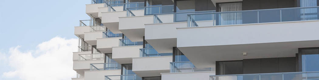
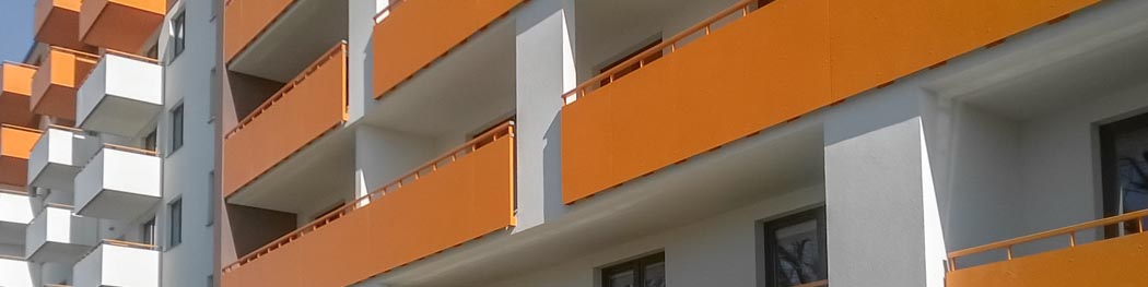
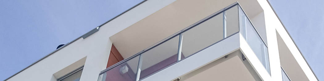
The set of Copal System elements can be used to make horizontal railings, secured to the horizontal or vertical surfaces. An example of a railing made of a set of Copal System elements is shown in Figure 16. Method of fastening the railing to the floor is shown in Figures 17 and 18.
Elements of railings made of aluminum alloys are coated with polyester or anodic oxide coating. Aluminium elements that are not visible after assembly can be used without protective coatings.
All connecting parts are protected against corrosion by means of a galvanized zinc coating or are made from
The required technical properties of the products covered by the Recommendation are given in clause 4
3. INTENDED USE, SCOPE AND CONDITIONS OF APPLICATION
The Copal System Railings are designed to protect against the danger of falling out by a person standing or moving along the surface secured with the railing.
Railings can be used to protect balconies, loggias, terraces, French windows or porches in residential buildings, blocks of flats and public buildings, to the extent resulting from the Regulation of the Minister of Infrastructure dated 12 April 2002 on the technical conditions to be met by buildings and their location (Journal of Laws No. 75 of 2002, item 690, as amended).
Railings can be used in residential single and multifamily buildings, office buildings, hospitals, nursing homes and public buildings with the exception of surfaces generally available to the crowd, such as concert halls, sports halls (including stands) and access ways at the railway station platforms.
Surfaces that are to be protected by Copal System railings should be classified in accordance with the criteria specified in
The floor to which columns are fastened should have a compressive strength of not less than concrete class C16/20 according to
For attaching railings to the floor, sleeve anchors or bonded fasteners should be used, approved for marketing and intended for a particular floor type, with a carrying capacity specified in the technical design.
In view of the corrosion protection, Copal System railings should be used in accordance with the requirements of
The use of Copal System railings should be in accordance with the technical design, developed for a specific facility, taking into account:
- applicable standards and building regulations, in particular
Regulation of the Minister of Infrastructure dated 12 April 2002 on the
technical conditions to be met by buildings and their location (Journal of Laws No. 75 of 2002, item 690, as amended).
- the provisions of this ITB Technical Recommendation,
- railings mounting instructions, developed by the manufacturer and delivered to the customers.
4. TECHNICAL AND UTILITY PROPERTIES. REQUIREMENTS.
4.1. Properties of materials
|
Elements included in the |
Copal System set should be made of the following |
|
materials: |
|
|
- fixing columns, handrails, mounting strips, feet and handles for mounting the |
|
|
columns to the floor should be made of aluminum alloy EN
|
|
|
|
T66 according to
|
with the requirements of
-
fillings should be made of laminated safety glass 8 mm thick, that meets the requirements of
-
retaining gaskets should be made of EPDM or thermoplastic elastomer (TPE) and should meet the requirements of
4.2. Properties of the railings
4.2.1. Dimensions Dimensions of the elements included in the set for making Copal System railings should be in accordance with the drawings 1+10.
Tolerances for dimensions and shape of aluminum profiles should to meet the requirements of
Tolerances for other elements of the railings should respond the medium class m according to
Railings made of Copal System elements should have the following dimensions:
-
height of the railings measured from the floor to the top of the handrail should not be less than H = 0.90 m for
- the clearance or hole size determined as the diameter of the circle inscribed between the elements of the filling of railings should not be greater than:
•
0.12 m - in the case of
•
no requirements - in the case of
• 0.20 m - in the case of other buildings,
- the distance between the railing columns should not be greater than 1.0 m.
4.2.2. The quality of workmanship. Elements of railings should be smooth, without cracks, dents, tears, sharp and cutting edges.
Profiles should be straight, without twists and permanent deformations.
Local flatness deviation in the profiles connecting points should not be greater than 0.6 mm.
Connections should be well fitted and easy to install and should be rigid, durable, and should not become loose due to service loads.
Retaining gaskets should adhere without folds and breaks into the relevant surface of the filling and the profile of the railing.
4.2.3. Resistance of the railings to static loads. The railing tested for resistance to static load (load chart as per fig. 19) after the test should be able to secure the protected space against the danger of falling out. After the test there may occur some permanent deformation of the railings, provided that the product continues to meet the safety features.
The railing should transfer static loads caused by:
- force F 1 acting perpendicular to the plane of the railings, with a value of 1.0 kN / m applied to the handrail at a height of 1.10 m, measured from the floor to the top of the handrail,
- vertical force F 2 acting on the plane railings, downwards, with a value of 0.5 kN applied to the handrail at two points located symmetrically at a distance of 0.15 m from the center of the span,
- vertical force F 3 acting on the plane railings, upwards, with a value of 0.5 kN applied to the handrail at two points located symmetrically to the column, at a distance of
0.15 m from the vertical columns of the railing,
- vertical force F 4 with a value of 1.0 kN, acting in the plane of the railings on the filling mounted to the railing.
4.2.4. Resistance of the balcony filling to hard body impact
The filling of the railings should withstand a single blow of a steel ball with a mass of 0.5 kg, falling freely from a height of 1.0 m. As a result of impact there should occur no puncture of the filling or loosening of any fixing part of the filling.
4.2.5. Resistance of the railings to dynamic loads. The railing should transfer dynamic load caused by hitting of a 30 kg bag, with the energy of 200 J. As a result of the impact , the filling should not be taken out of the fastening elements and there should be no punctures.
4.2.6. Properties of protective coating of aluminum parts. Aluminum parts of the railings should be protected against corrosion by means of:
- anodic oxide coating with a thickness of not less than 15 m,
-
polyester coating with a thickness of not less than 60 µm and degree of adhesion to the floor 0 according to
Anodic oxide coatings on aluminum profiles should be made by holders of the OUALANOD quality mark and should meet the Technical Requirements for the OUALANOD
|
Quality Mark set out in the approval arrangements no. UA GW 111.17/2011, |
Table 2 |
|
|
|||
|
Polyester coatings on |
aluminum |
profiles |
should be made by |
holders |
of |
the |
|
OUALICOAT quality mark |
and should |
meet |
the Technical Requirements |
for |
the |
|
OUALICOAT Quality Mark set out in the approval arrangements no. UAGW 111.17/2011, Table 1.
5. PACKAGING, STORAGE, HANDLING
Products covered by this Recommendation should be supplied in wrapping or packaging that protects the railing components against mechanical damage. Finished products should be stored and transported in accordance with the instructions of the Manufacturer, so as to prevent their technical properties.
Each package must be accompanied by a label containing at least the following information:
- name and address of the manufacturer,
- name and designation of the product and its intended use,
-
ITB TECHNICAL RECOMMENDATION number (RT
- Number and date of issue of technical certificate (certificate of conformity with ITB Technical Recommendation). Products covered by the Technical Recommendation may be marked with the following marks:
ITB TECHNICAL RECOMMENDATION No. RT
placed on the product or label. ITB logo may be black or blue.
6. ASSESSMENT OF CONFORMITY
6.1. General principles
The Technical Recommendation is a voluntary document, issued for products not subject to the requirements of Art. 9.1 of the Act of 16 April 2004 on building products (Journal of Laws No. 92/2004, item 881, as amended). It forms a technical specification that allows for the assessment of conformity and issuing technical certificates (or certificates of conformity), confirming the compliance of the products with the requirements of this document and may be produced to customers who purchase the products.
Technical characteristics of the products covered by the Recommendation should be attested by a technical certificate (certificate of conformity) issued by the manufacturer, after the assessment of conformity with the Technical
Recommendation RT
The basis for conformity assessment:
a) Initial type testing
b) Factory production control.
6.2. Initial type testing
Initial type testing is an examination to confirm the required technical and operational properties, performed before marketing the products. Initial type testing covers:
a) Resistance of the railings to static loads,
b) Resistance of the filling to hard body impact,
c) Resistance of the railings to dynamic loads,
d) Properties of protective coating of aluminum parts.
The tests, which in the Technical Recommendation procedure constituted the basis
to determine the technical and operational properties of products are the initial type testing in conformity assessment.
6.3. Factory production control.
Factory production control covers:
a) specification of materials and inspection of documents confirming their technical characteristics,
b) inspection and testing during the manufacturing process and testing of finished products (see 6.4), conducted by the manufacturer in accordance with a prescribed test plan and according to the rules and procedures specified in the documentation of factory production control, adapted to the production technology and aimed at obtaining products with the required properties.
Production control should ensure that the products are in conformity with the ITB Technical Recommendation no. RT
6.4. Testing of finished products
6.4.1. The test program. The program covers:
a) ongoing tests,
b) periodic tests.
6.4.2. Ongoing tests. Ongoing tests include checking of:
a) dimensions,
b) quality of workmanship.
6.4.3. Periodic tests. Periodic tests include checking of:
a) Resistance of the railings to static loads,
b) Resistance of the railings to dynamic loads,
c) Properties of protective coating of aluminum parts.
6.5. The frequency of testing
Ongoing tests should be conducted in accordance with a prescribed test plan, but not less frequently than for every batch of products. The batch size should be specified in the documentation of the factory production control.
Periodic tests should be carried out not less than once every three years.
6.6. The test methods
6.6.1. Verification of dimensions. Dimensions are verified by measuring with a universal measuring instruments tailored to the required accuracy.
6.6.2. Verification of the quality of workmanship. The quality of the workmanship
is verified by visual inspection of the elements for making the railings.
6.6.3. Verification of the resistance of the railings to static loads.
The resistance to static loads is verified on a sample consisting of two spans of the railing attached to the floor by means of three columns.
The resistance of the railing to load force perpendicular to the plane of the railing is tested according to the diagram shown in Figure 19 A.
The resistance of the railing to downward vertical force acting in the plane of the railing, is carried out according to the diagram shown in Figure 19 b.
The resistance of the railing to upward vertical force acting in the plane of the railing, is carried out according to the diagram shown in Figure 19 c.
The resistance of the filling to downward vertical force acting in the plane of the filling, is carried out according to the diagram shown in Figure 19 d.
6.6.4. Verification of the resistance of the balcony filling to hard body impact
The resistance to hard body impact is verified as specified in
6.6.5. Verification of the resistance of the railings to dynamic loads.
The resistance to dynamic loads is verified as specified in
6.6.6. Verification of properties of protective coating of aluminum parts.
The properties of the protective coating of aluminum parts are verified by measuring the coating thickness, in accordance with
6.7. Sampling for testing
The test samples should be taken at random, according to
6.8. Evaluation of test results
Manufactured products should be considered as complying with the requirements of this ITB Technical Recommendation , if the results of the tests are positive.
7. FORMAL AND LEGAL PROVISIONS
7.1. The Technical Recommendation no. RT
7.2.
The ITB Technical Recommendation no. RT
7.3. This Technical Recommendation does not infringe the rights resulting from the laws on the protection of industrial property, in particularly from the Announcement Marshal of the Sejm of 13 June 2003 on the publication of the consolidated text of the Act of 30 June 2000 - Industrial Property Law (Journal of Laws No. 119/2003, item 1117, as amended). Ensuring these rights is the responsibility of the users of this ITB Technical Recommendation.
7.4. ITB, by issuing this Technical Recommendation, does not assume any responsibility for any infringements of exclusive and acquired rights.
7.5. This ITB Technical Recommendation does not relieve the manufacturer from the responsibility for the proper quality of products and building contractors from the responsibility for their proper application.
7.6. Published booklets and advertisements and other documents related to the marketing and use in the construction of the set of elements for making Cipal System railings may include information on the ITB Technical Approval
No.
8. EXPIRY DATE
The Technical Recommendation no. RT
The validity of this Technical Recommendation may be extended for further periods, if the applicant or a formal successor files with the Building Research Institute a relevant application, but not later than three months before the expiry of this document.
THE END
Standards and related documents:
ADDITIONAL INFORMATION
i
Concrete. Part 1: Specification, performance, production and conformity.
Aluminum and aluminum alloys. Sheet, strip and plate. Part 1: Technical conditions for inspection and delivery.
Aluminium and aluminum alloys. Wrought products. Temper designation.
Eurocode 1: Actions on structures. Part
Aluminium and aluminum alloys. Extruded rods, tubes and
profiles. Part 2: Mechanical properties.
Windows and curtain walls, doors, blinds and shutters.
Door leaves. Determination of resistance to hard body impact
Aluminum and aluminum alloys. Coil coated sheet and strip for general applications. Specifications.
Aluminum and aluminum alloys. Extruded precision profiles in alloys EN
Aluminum and aluminum alloys. Extruded precision profiles in alloys EN
Building Hardware. Gasket And Weatherstripping For Doors, Windows, Shutters And Curtain Walling. Part 1: Performance Requirements and Classification.
General tolerances. Tolerances for linear and angular
dimensions without individual tolerance indications
Paints and varnishes. Determination of film thickness.
|
|
|
|
electrically |
|
|
conductive |
basis |
materials. |
Measurement |
|
|
of coating thickness. |
|
eddy |
||
current method.
Paints and varnishes.
Corrosion of metals and alloys. Corrosivity of atmospheres. Classification, determination and estimation.
Glass in building. Laminated glass and laminated safety glass. Laminated safety glass.
Approval arrangements UAGW 111.17/2011
Paints and varnishes. Corrosion protection of steel structures by protective paint systems. Part 2: Classification of environments
Statistical quality control. Random selection of sample products
Approval Arrangements for tests and evaluation in accordance with the technical requirements of quality marks QUALICOAT and QUALANOD, powder coatings and anodic oxidation coatings on aluminum and steel profiles and accepting the results of tests performed under the quality marks QUALICOAT and QUALANOD.
Reports of testing and evaluation
1.
Test report No.
2.
Test report no. L13013 COPAL SYSTEM Balcony Railing, Laboratorium Pomiarowo- Badawcze METALPLAST KARO ZŁOTÓW S.A., ul. Kujańska 10 E,
3.
Test report no. L13266 COPAL SYSTEM Balcony Railing, Laboratorium Pomiarowo- Badawcze METALPLAST KARO ZŁOTÓW SA, ul. Kujańska 10 E,
4.
Technical Opinion no.